B Using FEMM
Abbreviated, with slight additions, from David Meeker’s online guide (Meeker 2018):
B.1 FEMM
Finite Element Method Magnetics (FEMM) is a finite element package for solving 2D planar and axisymmetric problems in low frequency magnetics and electrostatics.
B.2 Obtaining FEMM
The program can be obtained via the FEMM home page at http://www.femm.info, and runs on Windows or Wine on Linux.
B.3 FEMM Magnetostatic Tutorial
Run the FEMM application and select New from the Main Menu Bar. Select Magnetic Problem from the pop-up menu. The new window should have a top menu bar similar to:

1. Problem Geometry
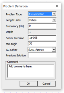
The first step is to set the problem type, this can either be axisymmetric or planar. Select Problem from the menu bar and a window will pop-up where you can set units and problem type. For this example, select axisymmetric and Inches for the units.
2. Draw Regions
Click on the node button  from the menu bar and press the tab key. This will allow you to type in the position of a point. Once all the points defining the geometry have been entered, click on the segment
  button. Then click on two nodes and a line segment will connect them. Make sure all regions are closed, coil, iron, air, etc. You then need to label the regions so you can refer to them later. Click on the label
  button in the menu bar.
3. Materials Properties
Select Properties then Materials Library. A popup window with available materials will appear.
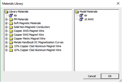
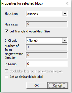
Select the materials for your model and drag them from the left (material library) column to the right (your model) column. You can now right click on the region labels and once the region label is red, press spacebar. This will pull up a properties box for the region. You can select the material for the region in the Block type pull down menu.
4. Circuit Properties
You also need to define your circuit or current region. This is done by selecting Properties and Circuits from the menu bar. You can name your circuit and select the total amps of the circuit. Then right click on the region label and press space bar to get the properties box for the region, as you did for the materials. In the image from step 3 above, there is an In Circuit pull down menu. Use this to select your defined coil/current for this region.
5. Boundary Conditions
Your model needs a boundary and boundary conditions. Select the boundary button  , and a popup menu will appear. Usually you can accept the suggested values in this popup window. Make sure to save the file.
6. Mesh
Click on the mesh button  and a mesh will be generated for your model. You can adjust the mesh size in the different regions by right clicking on the region label and pressing space bar. Then adjust the Mesh size. Once you are happy with the mesh, click on the calculate button
  .
.
7. Results
Click on the glasses button  to view the results. This will open a post processor window where you can plot flux densities, values at a point, values along a line, etc.
References
Meeker, David. 2018. Finite Element Method Magnetics. http://www.femm.info.