Run II D0 Muon Identification

The information below covers D0 muon ID. A FINAL PAPER was published in 2013 in NIM covering the effort from 1998-2013.

This we page gives an overview of Run II muon identification, including a brief description of the detector,coverage, trigger, and expected resolutions. Also, some comparisonsto the Run I muon ID will be included, as will some discussionsof backgrounds. Preliminary descriptions of offlinealgorithms and analysis tools are also given along with a pointer to software documentation.

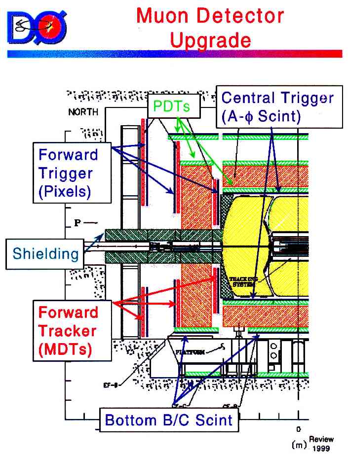
Muon reconstruction utilizes the inner tracking, thecalorimeter, and the muon detector elements themselvesto identify muons and determine their energy.

  • Run II Detector
  • Muon Detector

    The muondetector consist of scintillator and drift tubes, with effectively complete coverage out to |eta| of 2. As seenin the layout, the detector is split at |eta| of 1into a central and forward system. Each has 3 layers(usually called A,B,C with A between the calorimeter andiron and the other two outside the iron) of drift tubes(called PDTs in the central and MDTs in the forward; theydiffer in size with the PDTs being 4 x 2.5 inch rectangles whilethe MDTs are 1 cm squares with the PDTs also have timedivision measurement). There is also 2 or 3 layers of scintillatorcoverage with the forward scintillators sometimes called pixels,the central A-layer counters called a-phi, and the BC counterscalled the cosmic cap. Scintillator time is read out with botha 15-20 ns "trigger" gate and a 80-100 ns "readout" gate.

    The following figures show the central and forward muon detector eta and phi coverage .Detector coverage will be almost complete for high pt muons,with more than 75% hitting at least 2 layers and more than 90%hitting at least 1 layer (at |eta|<2). For A-layer muons, thereis no coverage for phi from 225 to 315 degrees for |eta|<1giving a geometric acceptance of about 85%.

    The detector thickness is in the range 5-9 interaction lengthsin the calorimeter, and 7-9 in the iron. The thickness is shown in:Thickness versus Theta .The plot indicates the thin spots at the CC-EC and CF-EF gaps. Itdoes not show the thin spot at phi=110 degrees in the central (dueto the main ring pipe) or the small loss of material on the bottomfor cables. Energy loss follows thickness, with 1 interaction lengthin the calorimeter or iron equivalent to 0.25 or 0.23 GeV/c energy lossrespectively. This gives a minimum energy of about 1.6 GeV for a muon to exitthe calorimeter, and about 3.3 GeV to exit the iron.

    Momentum Resolution

    Momentum Resolution will be measured using both the inner trackingsystem and the muon toroids. The momentum resolution (at eta=0)will be about .02+.002pt for the inner tracking and.18+.003p for the muon toriods (where the terms are added inquadrature). The first term is due to multiple scatteringand increases with |eta|. A Calibrationoverview describes expected muon detector resolutions.

    Digression on Run I Experience

    Run I top event 79 and top event 417 show the typical response of the calorimeterand the central muon PDTs; this will be similar for Run II muons. Inparticular, while the Run II PDT efficiencies should be better, therewill still be cases where the PDT hits are lost (or wrong) dueto the passage of other particles (our top event 417 is an exampleof this as its a-layer hits were due to a delta ray). We will alsoneed to pattern recognize two close muons, such as in event 79.

    Muon Level 1 Trigger

    The Level 1 Muon Trigger (L1MU) uses tracks found by the Level 1Central Fiber Tracker Trigger (L1CFT), scintillator hits in the muon detectors, and wire hits in the muon detectors to form user-defined specific triggers that are sent to the Trigger Framework (TF). The TF subsequently uses L1MU specific triggers to form global L1 triggers forthe experiment.The trigger information flow in the L1MU system is:
  • 1. Find muon triggers in octants using Muon Trigger Cards (MTCxx cards)
  • 2. Combine this information to form regional (N, C, and S) trigger decisionsin the crate manager (MTCM) cards.
  • 3. Form the user-defined specific triggers sent to the TF on the MTM card.

    The main weapons in reducing the L1 trigger rate come from matchingmuon detector hits to L1CFT tracks, imposing a timing window ( of about15-20 ns) to define scintillator hits, and forming centroids from wire detector hits in different planes.

    There are two types of triggers formed for each octant that wecall MTC05 and MTC10 for historical reasons. MTC05 triggers match tracksfrom the L1CFT to corresponding scintillator hits in muon detector. The L1CFT tracks include PT and sign information. The scintillator hits aredefined by having their times satisfying a modest time window (sigma = 20ns)about the expected time for a prompt muon from collisions. Scintillatorhits can come from one layer or as correlations of hits between layers.MTC10 triggers match centroids (stubs) formed from hits in the muon wire detectors with hits in the scintillator counters. Centroids can come from a single layer or as correlations of centroids between layers. MTC05triggers are primarily triggers in phi and MTC10 triggers are primarilytriggers in eta. Both can be used to define a good octant trigger.

    L1MU triggers can be user-defined using PT (four thresholds), region (|eta| < 1.0, 1.5, or 2.0), wire and scintillator quality (none, loose,or tight), and (for dimuons) sign (same, opposite, or either). Loosetriggers presently use a logical or of layers. Tight triggers presentlyuse a logical or of correlations between pairs of layers. Four CFT thesholdacan be used:

  • L1 Central LX Pt acceptance (4 thresholds)
  • Muon Level 2 Trigger

    The muon L2 trigger has available the complete time information,including calibration constants and PDT deltaT, for the wire and scintillatorelements. It also has scintillator hits which have beenread out using the wide gate in addition to thosechannels which passed the narrow L1 gate.Among other things it can do, it will improve on the L1correlation between the muon scintillator and wire hits,between the A-layer and BC-layer muon segments, and betweenthe muon segments and the central tracking. The scintillatortime resolution will be better due to using calibration andtime-of-flight corrections allowing better discriminationbetween fast, slow, and out-of-time sources. L2 should alsoallow better discrimination between 1 and 2 muon events,some punchthrough rejection, and an invariant mass determination(though with modest resolution).

    Rather than simply a rejection tool, the muon level 2 trigger should alsobe understood as an essential pre-processing stage for level 3. In fact, L3 will not unpack and scan the full muon detector readout, but will only unpack those modules in the neighborhood of tracks reported by L2. Thus, beyondbackground rejection, accurate muon object finding with ID qualityassignments are also main goals for the L2 algorithms.Muon level-2 processing happens in three stages. The time budget foreach stage is about 30 us on average.

  • 1. The SLIC cards receive front en data (after a fast calibration) and Level 1 output. Front end data undergoes highly parallelized processing into A-layer and BC-layer individual segments, with/out scintillator confirmation. Level 1 objects are rewritten in L2 format. L1 objects, A-segments and BC-segments are sent to the next stage, with global (physics) values for Pt, Eta, Phi, and scint times.
  • 2. The Alpha pre-processor collects all segments found, and searches for A+BC layer matches, with/out L1 confirmation. Calculates momentum (toroid only), assigns track quality (loose/tight) and a time stamp (prompt, slow, out of time).
  • 3. Global L2 collects the muon candidates from the Alpha pre-processor, as well as physics objects from all other L2 subsystems. Global can correlate different L2 objects, and confronts them with the L2 trigger menu. Event acceptance can be based on one or more physics objects, their interrelations, and/or simple event topology. Global L2 is the very first DAQ instance with access to the whole event, and able to perform event wide trigger decisions.

    Muon Level 3 Trigger

    The muon L3 trigger will utilize aspects of the offline muonreconstruction. The muon L2 will define geographic regions where L3 shouldunpack and track. L3 muons will have more complete informationon the vertex and inner tracking components which will yieldan improved momentum resolution, and the ability to requirethat multiple muons came from the same vertex. Fits done tothe muon detector elements will be essentially the same as inthe final offline reconstruction, and requirments on matchingthe muon track to the inner tracking can reduce any remnantcombinatorics plus punchthroughs. L3 will also use the calorimeterenergy to reduce combinatorics, plus also separatemuons into isolated and non-isolated. L3 will improve onL2's ability to seprate muon sources into prompt, slow, orout-of-time by fitting the available scintillator hits along atrack to the particle's velocity. L3 can remove remnant cosmicray muons both by their being out-of-time and by lookingfor evidence of a penetrating track on the opposite side of the detector.L3 can also clean up single muon events which L1 and L2 identified as dimuons,such as those which pass through the FAMUS-WAMUS overlap region.

    This document describes the muon-specific software to be used by the level 3 trigger. A user guide for Level 3 muon tools is also available.

    Trigger Simulation

    (to be written)A combined L1L2 simulation package d0trigsim;Individual simulation and analysis packages:tsim_l1muo, l1muo_analyze, tsim_l2muo, l2mu_analyze, l3fanalyze

    Muon backgrounds in Run I were from cosmic ray muons and combinatorics.For Run II, we have the additional ability to trigger and reconstruct lowerpt muons which hit only the a-layer.

    Punchthrough

    As the detector is thinner,a significant number of muons will be produced by punchthroughs whichwill be in time, but with energy and direction exiting the calorimeterwhich are not in agreement with the inner tracking's values. A Preliminary Punchthrough Study
  • has been done useparamterizations but GEANT-based studies are needed to fullyunderstand this background and how to minimize it.

    Cosmic Rays

    Cosmic ray muon backgrounds will be reduced from their Run Ivalues of a few percent for isolated muons by improvedscintillator timing and better central tracking information.In particular, most muon will strike at least two scintillationcounters with time resolutions of about 1 ns for the smallera-phi and pixel counters, and 2-3 ns for the large outer counters.This will easily discriminate between entering and exiting muons.

    Combinatorics

    Combinatorics were a significant background for Run I muonsin the forward directions. The rate in muon detector elements will be reduced by the new shielding, with theoverall combinatoric background also being reduced to a (hopefully) insignificant level by having a more capablecentral tracker. Combinatorics will remain a significantsource of muon triggers. Many of the detector hits will be due tointeractions at low angles which produce particles (mainlyneutrons and gammas) which exit ("sneakthrough") into themuon system. As they have longer path lengths, and often slowervelocities, such hits will be out of time. This is seen in aA-phi Run I timing study , and is alsoobserved in Run II Monte Carlo events.This chapter describes muon utility software packages usedat various stages of data processing and in on-line detector monitoring.
  • Muon Indexing
  • Muon Geometry
  • General Utility Functions
  • Muon Online Monitoring (Examine)
  • Muon Detector and Event Visualization (D0Scan)
  • Muon Detector and Event Visualization (d0ve_muon)
  • (to be written)

    Muon base geometry (positions, orientation, and dimentions of muon detector elements)is fully described in MuoBaseGeometry.rcp

    The offline muon identification is based on a match between a charged particle detected in the central trackerand a signal in the muon system. Charged particles are objects made by associating tracks detectedin the SMT and CFT detectors, jointly called GTracks, and reconstructedvertices.To be used as a seed for a muon object, a charged particle is required to have transverse momentum greater than 1.5 GeV. The signal detected in the muon system can be a track penetrating thetoroid, a track segment reconstructed inside the toroid (and A-layer segment), or just a set of hits detected in the muonsystem. The recontruction steps, from raw data to muon objects, and data "chunks" containing object created at each step, are summarized in this chart.

    Unpacking Muon Raw Data

    (to be written)

    Hit Reconstruction in the Muon System

    Hit finding documentation

    Track Segment Reconstruction in the Muon System

    Processed wire and scintillator hits are used as input to the recontruction of track segments inside and outside the toroid(cvs package muo_segmentreco).Segments are characterized by the fitted "center of gravity" and direction, and have links to the associated hits. There are currently two algorithms available: a "combinatorial" algorithm by O. Eroshin and A. Kozelov, and a "Linked List" algorithm by O. Peters. As of D0reco production version p08, the default is set to using the LinkedList algorithm.

    Track Finding and Fitting in the Muon System

    Track segments reconstructed inside and outside the toroid serve asinput to the track finding and fitting package (cvs package muo_trackreco).The result of this procedure is a MuoTrack object: a muon track reconstructed in three dimensions, in the muon system alone.

    Offline Muon Object

    The last step in the offline muon reconstruction is combining theresults of the data processing in the muon system with theinformation provided by the central tracking system and the calorimeter,and constructing a muon object suitable for physics analysis.

    Global Muon Fitting

    It is anticipated that the global muon track fitting will utilizethe extension of the algorithm applied in the track fitting in the muonsystem, described in the previous section (the so called "Saclayalgorithm").In this application, the input consists of a central track (GTrack foundusing CFT and SMT data), and track segments found in the muon system inside and outside the toroid (MuoSegment objects). Both calorimeter and the toroid areapproximated by two thin scatterers, placed at the distance d/sqrt(12) from the outside walls, where d is the appropriate detectorthickness.

    The global fit further constrains track parametersas compared to the parameters determined in the central tracking alone,although the effect is modest due to the large MCS effects in the calorimeter. The biggest effect is expectedin the forward region, where the central tracking lever arm is reduced,and at the largest transverse momenta. The main advantage of theglobal fitting is the availability of the chi-squared as a propermeasure of the quality of the central - muon track matching.

    The above algorithm requires a line on each side of the thickscatterer: the measurement of the position and the direction,or at least a line and a point,which means at least three space points along the track candidatein the muon system, with at least one outside the toroid.This is possible only for tracks with energy sufficient topenetrate the toroid. Moreover, the detector coverage is limited,notably there is a hole in the A layer coverage in Wamus at the bottom,to allow for the calorimeter support.In the case when the track leaves no hits outside the toroid,the fit can still be performed, using the central track and an A layersegment.

    In the case of no hits in the layer,it is appropriate to extend a GTrack to the BC layer and to apply a simpletest of the track - segment matching, using the Geant-motivated size ofthe extended track position uncertainty.

    Note:
    In the present version of the muon reconstruction code (cvs package muonid)this simple matching of the central track and the A layer segment, without re-fitting the track, is applied toall candidates. The successful match between the central track extendedto the A layer, and an A layer segment, is the basis for making a muonobject. The matching criteria are set through the rcp file.In particular, the tolerance on the match in the drift coordinateis parametrized as const1/pt + const2, with the values of theconstants set using the spread of the track arrival pointobtained in Monte Carlo studies.The parameters of the central track are copied to the muon object.

    The figure below shows the the momentum resolutionfor a muon track reconstructed (with preco04), separately in the muon detector (MuoTrack) and in the central tracking system (GTrack) . The results for MuoTrack wereobtained with single muon MC studies, with no backgroud added. The results for Wamus (red points) were obtained with the track fitting package described earlier. The results for Famus (blue points)were obtained withan earlier version of the muo_trackreco package, where track momentumwas obtained in a one-step calculation using the bending angle in thetoroid. The results for GTrack were obtained using a J/psi sample with1.1 MB events on average (a green square at pt=3.7 GeV), and a Z sample with 0 (a green triangle at pt=37 GeV) and 1.1 MB events (a green squareat pt=37 GeV).

    Muon Tracking in the Calorimeter (to be written)

    Muon Object Definition

    Muon object (its name in D0reco is MuonParticle) is oneof the reconstructed physics objects that will be available in the Thumbnail (TMB) files that willalways reside on disk, for all data collected in Run II. Hereis a summary of the proposed muon contributionto TMB. Here are the contents of the PMUO Zebra bank used in Run I.

    At the core of the offline muon identification is a globaltrack that uses the information from the central tracking,muon system, and (optionally) calorimeter. A global track contains the basicinformation on the parameters of the reconstructed muon and onits quality: momentum vector and the z coordinate at the point ofclosest approach to the z axis, the value of the distance of closest approach, and the error matrix. This information (20 floating point numbers) is sufficient torefit the track with additional constraints, e.g. under the hypothesisthat the track originates from a dimuon resonance.

    The quality of the fitted track depends on the fit chi-squared and the number of hits from various subdetectors used in the fit.A more sophisticated quality definition should use the informationon the probability for a given trajectory to miss a given set of layers.(An appropriate tool is in preparation).

    An additional test of track quality is provided by the muonscintillator counters.For the track trajectory constrained by the global fittting,it is possible to calculate the sum of the time of passage from theinteraction point to the countertraversed by the track and the time of the light propagation insidethe counter, and to compare it with the measured time. Combining theinformation for the counters inside and outside the toroid allowsthe measurement the track velocity, and thus further improvement of theseparationof prompt muons from cosmic rays and, possibly, to identify slow, penetratingparticles.

    Muons produced in pbar-p collisions may be isolated or imbeddedin jets. The best information on muon isolation comes from the calorimeter.As in Run I, we intend to search for a track-like object in the calorimeter,consistent with the muon trajectory, and to use the information on theenergy deposited in neighboring cells to determine the track isolation.The most useful parameters from the muon tracking in the calorimeterare: sum of energy of hit cells (ETRACK), energy in a 3 by 3 towercentered on the muon track (E33), and the fraction of hadronic layerswith energy (HFRAC). The other definition of track isolation, basedon the association with a jet is also used. In this case, the (muon,jet) system constitutes a separate object, a "bcjet".This object is being developed by the b ID group. For the muon object,it is sufficient to point to the possible bcjet, since both kinds ofobjects will always be included in any data format, including TMB.

    Independent of the track isolation measured in the calorimeter,the central tracking system provides information on all charged tracks(with pt > 0.5 GeV) and their momenta, emitted in a cone (of 0.5) around the muon.

    Analysis Package

    An analysis package, muo_analyze, making use of all the available methodsfor retrieving muon reconstruction results, is documented here. The package makes a root (or PAW) ntuple, includingMC muons, all GTracks with pt>1.5 GeV, muon hits, segments, localtracks, and the final muon objects, MuonParticle's. The documentation provides instructions how to run the analysis program,and includes example macros for an analysis of a root file.The package muo_analyze can be run independently (as described in theabove documentation) or as part of the overall event analysis, reco_analyze if the user is interested in other reconstructed objects (jets, electrons, etc).

    Back to the Muon ID page
    DØ Home Page


    Last modified: Feb, 2001

    hedin@niu.edu

    Daria Zieminska